A comprehensive guide to setup a DIY Raspberry Pi-powered and Cloud-backed hamster wheel speedometer
Dr. Heiko KromerStepan Gaponiuk
This blog post is Part one in a series of three blog posts where we describe how to stream data from a Raspberry Pi into the Cloud.
Part one focuses on setting up the hardware and sensor that we will use with the Raspberry Pi.
Parts two and three will cover setting up resources in the Cloud to stream Internet of Things (IoT) data into the Cloud. This will be done in two parts, showcasing the solution for two hyperscalers — the AWS (Amazon Web Services) and Microsoft Azure Cloud.
Introduction
Have you ever looked at your hamster frantically running in its wheel for hours on end and wondered how fast they were running? How far they traveled each night? If you do not have a hamster, are you curious how to track how often a door in your home was opened? Do you want to monitor how often you have given in the temptation of your favorite cookie jar?
All that you need to bring to follow this blog post are some Python skills, a Raspberry Pi microcontroller, and the willingness to tinker around with the Raspberry Pi. I am going to present the use case of a hamster wheel speedometer. It will be fun and no hamster has been harmed and will be harmed following along the steps outlined here.
In this blog post, we will set up a small single-board computer to build a speedometer for a hamster wheel. The number of rotations of the wheel is recorded passively with a (normally open) Reed switch and read out with a Raspberry Pi. In an upcoming blog post, we will write some Python code to process the data, store it locally and stream it into the Cloud.
If you are not a hamster aficionado, you can still take inspiration from my work. The low-cost Reed switch sensor that we use works well with earlier outlined cookie-jar or similar scenarios. Your imagination is the limit.
The main structure of the blog post is as follows:
- Requirements
This section lays out what is required to follow the steps described in this blog post. - Setting up the Raspberry Pi
In this section, we will connect the sensor to the Raspberry Pi and set up the Python environment. - Connecting and Testing the Reed switch
This section covers the Python script that we develop to read the Reed switch signal — the Reed switch is the sensor we will be using. We are storing the data locally on the Raspberry Pi.
The code is included in this GitHub repository:
https://github.com/kromerh/hamsterwheel
1 Requirements
To follow all the steps described in this blog post exhaustively, you are going to need the items from the shopping list below:
- A hamster
I am serving my time in service of a demanding little fur demon named Wilson. She’s a Golden Hamster, i.e., rather big. Any other type of hamster or rodent with sufficient activity in their wheel will also work. However, do not take this blog post as the sole reason to pick up a hamster. Make this decision consciously and be aware that they (hopefully) will spend a few years at your side. If you want to figure out if a hamster would be for you, you can read up on this, e.g., here. - A hamster wheel
Note that it should be large enough so the back of the hamster does not bend and it should not have a mesh to be gentle on their feet. - Super Glue for gluing a magnet to the hamster wheel
I used my 3D printer to print a custom-made holder for the Reed switch sensor. Because the hamster likes to dig tunnels, I had to fix the base of the hamster wheel as well. With some minimal craftsmanship, you should be able to fix something together that works in your case. I am happy to share the CAD models of the holders I built in case you have a similar setup as I have. Make sure that the set up is arranged so that the rodent cannot reach any of the electric components or cables. - A Raspberry Pi microcontroller (including power supply and microSD card)
I used and tested the code with both Model 3+ and Model 4. For the initial setup, you will need an HDMI (the model 4 needs a micro HDMI cable) cable, a USB keyboard, and an external monitor to connect to. You can find bundles/kits that are usually cheaper compared to buying the individual components. - A normally open Reed switch
The idea behind a (normally open) Reed switch is that the switch closes a normally open circuit in the presence of a magnetic field. There are various variants, I am using one from Adafruit. It consists of a magnet piece and the sensor part. Connecting the sensor part to one of the General Purpose Input Output Pins (GPIO) of the Raspberry Pi allows detecting a signal when the magnet touches the sensor part. It is a passive sensor in that it does not produce an active signal so there is a minimal (but not nonzero) risk that something will break if the cabling goes wrong. - Two female-to-female jumper wires
They are usually sold in bundles, e.g., here. The colors do not matter.
2 Setting up the Raspberry Pi
I am assuming that you got a brand new Raspberry Pi, fresh from the conveyor belt. I have written the below steps with the Raspberry Pi Model 3 B+. Make sure to check the correct pinout for your Raspberry Pi model — the latest model 4 has a different pinout.
Step 1: Installing the operating system
- Depending on the type of bundle you bought, it might be that the operating system — it is called “NOOBS” — is already preinstalled on the SD card. If it is, you can skip this step described below and jump straight to “Step 2”.
- Go to the official Raspberry Pi website and follow the steps to get NOOBS on your microSD card.
- Install the microSD card in the appropriate slot. If you have a case, you usually have to mount the Raspberry Pi into the case first and then insert the SD card. Connect to the Raspberry Pi an external monitor and a USB keyboard.
- Plug in the power supply, there should be yellow/red lights on the board. You should also see a colored square on the external monitor. Wait until you see a welcome screen.
- There is some initial setup, such as setting user account and password, connecting to a wireless network, localization, and others. These steps are self-explanatory. If you struggle, there are some excellent guides only a web search away. Make sure to note down the username that you select and the password. In memory of the hamster that served as an inspiration for this blog post, I named my user account “wilson”. For you, the default might be “pi”.
- To configure the Raspberry Pi to accept remote connections via secure shell (SSH), we have to open a terminal. By default, this should work with the shortcut CTRL + ALT + T. You can also use the Windows button on the keyboard to open the menu and navigate from there to the terminal application. In the terminal, type:
sudo raspi-config
- In the interface that will open up, select “5 Interfacing Options”, and press “Enter” and “P2 SSH” in the menu that will appear. Press “Enter” again and confirm with “<Yes>” that you would like the SSH server to be enabled. Confirm with “Enter” in the confirmation box and navigate down to “<Finish>” to close the tool. If you have trouble, there is a lot of documentation on how to enable SSH on the Raspberry Pi.
- Restart the device. If you are looking for the shut down button, stop. There is none. You can just unplug the power supply and reconnect it.
- Open a terminal of your choice on your primary machine (i.e., not the Raspberry Pi) and connect to the Raspberry Pi using the command:
ssh wilson@<ip-address-of-raspberry-pi>
- You will be prompted to enter the password you have chosen in step 5. Note that if you have chosen a username other than “wilson” when you set up the Raspberry Pi , you need to use this username to connect.
- You must find the IP address of the Raspberry Pi, e.g., by checking the devices connected to your WiFi router. Alternatively, you can open a terminal locally on the Raspberry Pi (it should have booted back up by now) and use the “ifconfig” command. Search for the IP address listed in the section of the adapter “wlan0”.
- There might be some warning about the inability to establish the authenticity of the host when connecting via SSH. We confirm that we would like this host to be added to the list of known hosts by typing “yes”. If you have connected to a different host with the same IP address before, there will be some conflicts in the […]/.ssh/known_hosts file. Either the prompt invites you to remove the line or you have to manually edit the file and remove the line. Searching for the IP address is the easiest approach in that case.
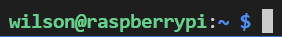
- If the connection was successful, the line in the terminal will read “username@hostname”, like so:
- Next, update the device using these two commands:
sudo apt-get update
sudo apt-get upgrade
- The first command will fetch the latest version of the package list from your distro’s software repository and any potential third-party repositories. The second command downloads and installs the update for each outdated package and dependency. This might take some time and you have to confirm with “y” to install the updates/upgrades.
Step 2: Setup the Python environment
- We will create a virtual python environment and install packages in this environment. It’s best practice to set up a virtual python environment for different projects. We can do this with these commands:
python3 -m pip install virtualenv
python3 -m venv env
- Activate the environment with this command (if you installed the environment in a different location other than the home directory, you need to replace the “~”-part with that location):
source ~/env/bin/activate
- The line in the terminal should now look like this:

- Observe the “(env)” at the beginning of the line.
- In our newly created environment we will need some packages installed, so run these commands to install them:
python3 -m pip install RPi.GPIO requests awsiotsdk boto3 botocore
- RPi.GPIO” is needed to communicate with the GPIO pins. The other two packages are not needed for this blog post, but for the second one in this series. “requests” is for the MQTT library that we will be using, and we will base the communication with AWS on the AWS IoT Device SDK v2 for Python, a.k.a. “awsiotsdk”. Boto3 is the Python SDK from AWS.
Perfect, the Raspberry Pi is set up and ready to go!
3 Connecting and Testing the Reed Switch
As in the previous section, I am assuming that you are using a Raspberry Pi Model 3 B+. If you are using a different model, you have to search for the respective pinout and make sure that you connect one cable of the Reed switch to a GPIO pin and the other one to Ground.
Step 1: Turn the Raspberry Pi off
- Before connecting the Reed switch to the Raspberry Pi, make sure that the device is turned off. Remove the power cable. Manipulating circuits that are connected to the Raspberry Pi while it is running carries the risk of damaging the device.
Step 2: Connect the Reed switch to the Raspberry Pi
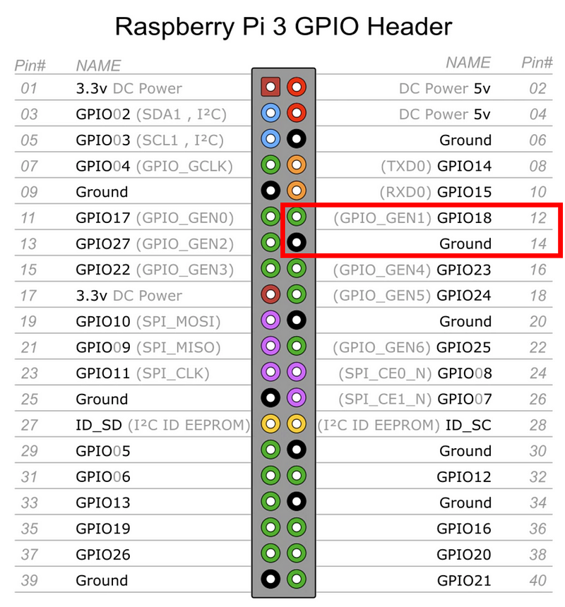
- Connect the two female-to-female jumper wires to pin numbers 12 and 14 (corresponding to the 6th and 7th pin in the upper row from the left). Depending on the version of your Raspberry Pi, the GPIO pinout might be different.
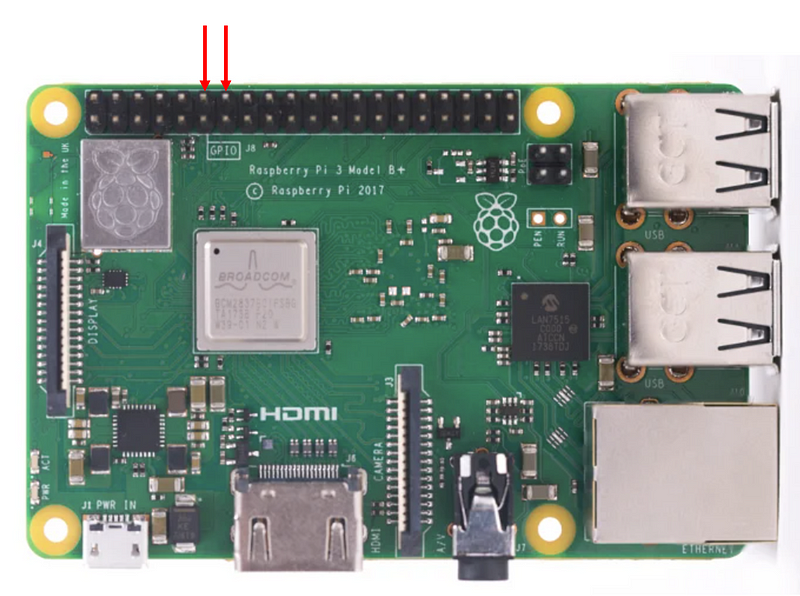
- Connect each of the two male parts of the Reed switch to each one female jumper wire. In the case of Model 3+, we have now connected the Reed switch to GPIO18 and Ground, respectively.
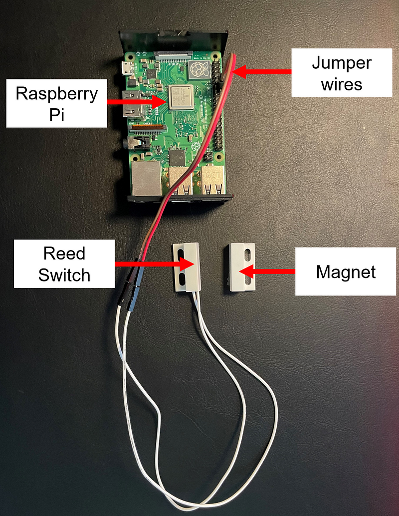
Step 3: Check the setup / compare to how it should look like
- This is how the setup should look like:
Step 4: Turn power back on
- Plug back in the power cable into the Raspberry Pi and connect to it via SSH.
Step 5: Clone the GitHub repository
- Create a directory to store the GitHub code on the Raspberry Pi by typing:
mkdir ~/repo/
- Create another directory that will contain the log files by typing:
mkdir ~/logs/
- Navigate into the repo directory:
cd ~/repo/
- Clone the repository (https://github.com/kromerh/hamsterwheel):
git clone https://github.com/kromerh/hamsterwheel.git
Step 6: Modify the readout script
- You are invited to read through the script (the main file is hamsterwheel/src/python/hamsterwheel.py). It currently supports two readout modes: One with logging locally the sensor data on the Raspberry Pi and another one streaming the read-out data into the AWS cloud. For this step, we will just select local logging mode. It is possible to use both modes — local and AWS — at the same time.
- In case you have a different username or cloned the repository in a different path, you need to adjust the script, namely in the file hamsterwheel/src/python/constants.py/ you need to change the paths in lines 11 through 13
# RPi paths
HOME = '/home/wilson/'
REPO = 'repo'
LOGS = '/logs/'
- Double-check the wheel pin definition as per your GPIO pinout as well. This is set in hamsterwheel/src/python/hamsterwheel.py in line 177.
- You can also modify the deadtime setting — i.e., how quickly the script loops — if you want a faster / slower readout. But be aware, if you make the deadtime very small (i.e., the loop will run fast) and you have enabled local logging, the storage on the Raspberry Pi might run out quickly in the order of a few hours. Also, depending on the speed of your rodent and the size of the wheel there can be multiple sensor readings per one circulation of the wheel if the readout time is too high. This needs to be adjusted in later data analysis, otherwise you gravely overestimate your rodent’s cardiovascular exercise abilities.
Step 7: Run the readout script (local mode)
- Activate the Python environment we created:
source ~/env/bin/activate
- Run the readout script (make sure the environment that we created is activated, i.e., “(env)” is written at the beginning of the terminal line):
python src/python/hamsterwheel.py
- You should see these log messages:
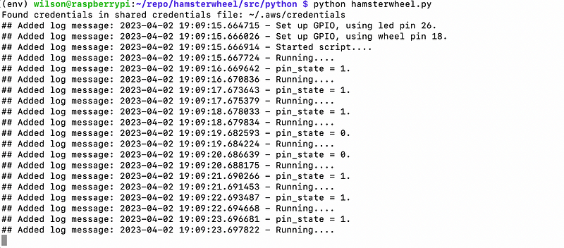
- As you can see at timestamp […] 19:09:19 I held the magnet next to the Reed switch and the output signal switched from 1 to 0. When I put the magnet away again, the state changed back to 1. Make sure that the sensor works by checking that the pin_state flips when the magnet touches the sensor.
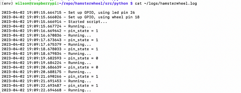
- You should also check if the log files are populated as well:
cat ~/logs/hamsterwheel.log
- Note that if you would want to start the readout script at startup, you can edit the crontab and use the .sh function that I placed in […]/src/bash/. You can also add a line in the crontab that makes sure the log file is overwritten every few hours. This will prevent out-of-storage problems with the Raspberry Pi.
- Alternatively, you can store the data locally on the Raspberry Pi in a MariaDB database. I will not cover this here, but setting this up is straightforward and there are many detailed guides. Full disclosure, at the beginning of this project I relied on local storage and lost a few weeks of previous data when the SD card of the Raspberry Pi died and of course I had not made a backup. The failure of an SD card is unfortunately not uncommon. This serves a good example of why storing IoT sensor data in the cloud is a huge advantage over local storage — and a valuable lesson for me.
With the Raspberry Pi set up and the circuit assembled and tested we are ready to stream the signal into the Cloud and continue to refine our hamster speedometer.
As a last step, you have to mount the Reed switch so that the magnet passes the sensor closely when the wheel is turning. This depends largely on the set up of your cage. If the distance between the sensor and the magnet is too large, you can try a stronger magnet.
I hope your hamster is ready and as excited as we are to jump into Part two in this series of blog posts!
Conclusion
In this blog post, I have shown you how to set up a Raspberry Pi from scratch and build a circuit to record a signal from a Reed switch. The purpose of this DIY project was to record data on the activity of a hamster in its wheel. The same setup can serve as a monitoring system for a door or a box.
These are the step-by-step introductions that were part of a workshop in the last years edition of the Growing Together Conference of D ONE and in a separate workshop that D ONE hosted jointly with the Analytics Club of ETH Zürich. Be sure to check out the next blog post in this series which explains how one can stream the signal that the Raspberry Pi recorded into the Cloud.
Thanks for your time and if you have any feedback or ideas how you can make use of IoT and the Cloud, let me know!